RTFM!

Posted in Uncategorized on February 18, 2010 by xeracy

…or at least know stock features before attempting to add your own.

I recently got a used ’94 GMC Vandura. The thing is a beast, but its radio lacks a tape deck. So i decided to re purpose my old DLO car iPod dock and FM transmitter to take an audio signal in.

I pulled the thing apart, documenting as i went to post on this very blog. I got extremely lucky as my first three wire guesses were spot on (Audio Gnd, L-Channel, R-Channel). Withing 15 min i had audio coming out of my computer, into the transmitter and out of my alarmclock/radio!

I began looking for a good place to solder my leads when i noticed something odd. It looked as though the traces led straight to the audio jack on the side of the unit! I couldn’t tell for sure, so a quick rearranging of plugs and i had the same result as tapping directly into the dock’s leads.

I swallowed my pride, having thought this project was almost done, when in actuality, it was never needed to begin with.

Lesson Learned. RTFM or know a device’s stock feature set before modding unnecessarily.

Augmented Kazoo

Posted in Art, Design, and Imaginary Existance, As Built on November 2, 2009 by xeracy

Well halloween has come and gone. I made a  Silly String Pumpkin as seen on Instructables via Hack-A-Day, but my servo motor died the day of halloween after all the stores had closed.  Needless to say, it was a sad halloween for hobby tech.

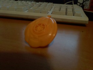
Anyhow, I got home from work today, and was playing with a toy kazoo shaped like a pumpkin (also had a bat, spider, and skeleton).

1102092245

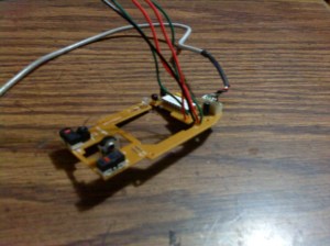
I figured it would be cool if the amount of control you had over the noisemaker could be translated into something like mouse movement for DJ scratching software, or something akin. I set to work desoldering the IR encoder from a usb mouse and adding leads for remote mounting. For a first pass, I used the  mouse hardware in lieu of an arduino build from scratch.

1102092208

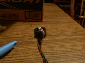
While holding the ir led and sensor in place on either side of the kazoo, i was able to control the vertical movement of my mouse, up and down. Unfortunatly, since hot-glueing the components together, it seems the mouse only goes down unless it is spinning quite fast. I understand that the encoder wheel from the mouse and the noise-making fan inside the kazoo have completely different timings, so i will next look into fixing that issue. Perhaps I can use the original mouse encoder wheel and a custom tube to make a version 2.0….    yeah, probably not.

1102092245

Anyhow, heres a quick demo video of my project thus far.


The Banshee: Quick-Implementation Audio Rifle

Posted in As Built, Hacks, Mods, and Misjudgements with tags on May 11, 2009 by xeracy

I found a local store (www.allelectronics.com) with bins and boxes full of loose electronics, old devices, overstock, crap, ancient electronics, and everything else your neighborhood RadioCrap doesn’t. On my first shopping spree today I found a small 110 db 12v siren.

After scrounging through some closets, I came across the perfect housing to weaponize my new screamer: an 18″ plastic margarita/frozen drink collector cup from Las Vegas. Its got a large base and 12″ of neck just about the size of the siren. The kicker is the neck of the container, which flares outward in a cone.

I cut up the base and using some zipties and a plastic cup, I mounted the Siren inside, butted up to an 8xAA Battery pack. I used a wooden clothespin and some wire to make a momentary contact switch and stuffed all the wires back inside.

The best feature is the long neck and flared neck which prevents the sound from having devastating effect on the operator.

I would post pics, but I dont think this one merits any really. Its a 10 minute throw-together.

New projects…

Posted in Uncategorized on September 26, 2008 by xeracy

I’ve got a few projects that I’m starting now.

First, If you have ever had a college class in a large lecture hall, chances are you’ve had to purchase a wireless remote (like an iClicker) that provides attendance checking and multi-button responses for in-class multiple choice questions. If you have been alive and not hiding under a rock for the past few years, chances are that you have played Guitar Hero (or rock band, I guess). Now I would like to draw the obvious comparison between the iClicker and Guitar Hero guitar. Both have five buttons. Now, I don’t have a class that requires an iClicker, but my friend Eugene does. He has kindly donated his for this project, and he will reap the benefits of having to lug a toy guitar to class!  I ordered a wireless PS2 Guitar off ebay for 20$ and it arrived earlier in the week. I finally got my hands on the iClicker today and I have one week until I need to either give it back to my friend (functioning and finished) or buy him a new one.

The second project still in design is a steam-punk device. I can say it has turbine powered illumination… Well you’ll see some sketches and schematics soon enough.

I’ll be getting some images and project pages up for these two soon!

10x SD Card

Posted in As Built with tags , , , , on September 4, 2008 by xeracy

Class Final Project: Create a prop of something impossible to acquire or create an object ten times its normal size.

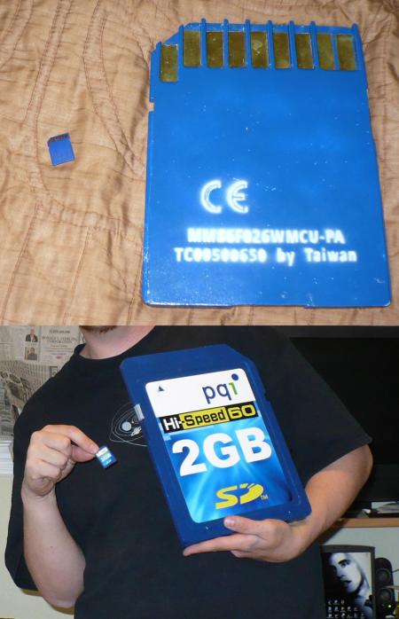
My Project: 10 x  SD Card

10xSD Card

10xSD Card

Materials:

  • 12″x48″x1/2″ Wood (poplar, a poor, yet workable choice)
  • Sheet Brass
  • Photo Paper (satin finish)
  • Spray paint (blue, white primer)
  • Wood Glue
  • Brass Wood Adhesive (no idea what I used, possibly spray stuff)

Procedure:

First off, let me just say ‘Thank You’ to whom ever needed a high def macro photo of the item I happened to choose. It makes creating a model much simpler. I took the macro image (actually more than 10x the size of the actual card) and scaled appropriately in AutoCad. It was easy to determine dimensions of most bits, as its was based in metric millimeters and was easy to  scale up. I layed out the front and back at 1:1 scale and plotted it out similarly.

Since I wanted to duplicate the fabrication of a real SD card, I planned on sandwiching two halves together. The front half features the label, on a slightly recessed plane, and a rounded linear groove along the bottom. The back has teeth along the top, to allow access to the contacts. There is also notches for the lock switch, etc.

Now, with templates and dimensions in hand, I began preparing the wood. I make the mistake of choosing too soft of a wood. Poplar, while it seemed appropriate, did not plane easily. I had a 3/4″ thick piece of lumber that I needed to plane down to one centimeter thick. I used a table saw with a datum blade to remove a good amount of thickness, but only 1/2″ strips at a time. The uneven finish i was left with was simple to sand down, but those faces would be on the inside of the card, so i didn’t bother doing a great job.

I used some light spray adhesive to attach the templates to the wood. A skill saw made cutting all the various angles and notches a breeze. At this point, it was beginning to look like an sd card.

My biggest hurdle was planing an 1/16 off the face where the label sits. I used a router table with a 3/4″ circular bit to remove the outer edges with the rounded corners. Then i used an electric hand sander and hand planer to lower the raised center. This was a bad choice, to say the least. I was using too dull of a blade on the planer and I had to constantly replace the sandpaper as it was getting worn down fast. Eventually I got a relatively flat surface that I could cover with the label later on.

Finally A 3/8″ rounded tip bit on the router was perfect for the rounded groove at the bottom of the card, finishing off all the cutting. Then I did a final sanding with a progressively finer grit.

I used a white base coat before a adding few coats of primary blue spray-paint. Then, I meticulously cut a stencil for the “Made In Taiwan” and Serial Number and used some gray paint to add it to the back.

I cut strips of sheet brass and used a metal/wood spray adhesive to attach them between the teeth on the back side. Finally, I used paper spay adhesive to affix the label to the face.

For my first real solo woodworking project, I consider this a major success, yet if I had to do it again, I defiantly would have made some better choices.

UPDATE:

In reply to the comments… I just wanted to join this club with Disk Guy and CD Lady…

Disk GuyCD Lady

Easy ESCape

Posted in Hacks, Mods, and Misjudgements with tags , , , , , , , , on August 13, 2008 by xeracy

Ever since I saw a Staples’ “Easy Button” hacked to play back pre-recorded messages, I have wanted to do something in a similar vein.  So, two months ago, while at Staples, I splurged $5 and bought an Easy Button. God, what an annoying little device. Skip ahead to the present when I finally got off my ass and busted the damn thing open.

So what should I do with such an obviously large button? Well, I know I’ve been smashing the ESC key on my keyboard at work a lot recently, so why not make it a single button keyboard?

Parts:

  • Staples’ Easy Button
  • PS2 Keyboard (cheapest one possible)
  • Wire

Tools:

  • Screw Drivers
  • Dremel Tool
  • Soldering Iron/Solder/Etc
  • Multi-Meter
  • Hot-Melt Glue
  • Jumpers (alligator clips connected by a short wire, for testing)

Preparation:

The first keyboard I could find in my office’s junk storage room happend to be light and simple. I cracked it open and found the entirety of the electronics to reside on a PCB less than 2.5″ x 1.25″. The easy part was tracing the leads for the ESC key to PCB pinouts. I literally used a sharpie to trace the lines to their source.

I then gutted the Easy Button. Small screws made it a quick disassembly with no breaking of plastic or need of force. The speaker popped out easy enough and even though I cut the leads to the batteries, the sound module and speaker are still intact (possible for a little circuit bending :). Originally, I was going to try to place the keyboard PCB where the Button’s PCB was, but it was just too long. I had to relocate it to the very bottom of the button, requiring me to cut away parts of the battery and speaker holder with my handy-dandy Dremel Tool (Best. Purchase. Ever.).

Now that I had a good idea as to the layout, I needed proof of design. So, using the jumpers and googled pinouts, I wired up the parts and plugged it in to a computer. HUZZAH! I successfully connect two wires to close a dialogue box in windows.

A little bit of soldering later,  I place the PCB in the button, and make sure all the parts fit together snugly. Now to make it permanent, I used a hi-heat glue gun to keep the PCB in place. The next bit of plastic on top of that was next to get glue. I soldered a bit of metal on the end of one of the ESC key leads and glued it underneath the metal spring from which the button gets its action. The other lead wouldn’t adhere to metal spring, so I had to bust one of my Dremel bits to put a hole big enough for a wire to go though in it.

That was it! One last demo before closing the case up for good.

… well this is bad… some extra buttons are apparently being activated, as when plugged it, IE flashes incessantly into full screen. And because I used hot melt glue directly on the PCB, there’s no way to re-solder the bad leads.

So, with a failed project on my hands, I closed up the case, cleaned up, and put it on my ever present Shelf-of-Failures.

Perhaps my Telephone Handset hands-free conversion will have better success…

After thinking it over…

I’ve come to realize what went wrong. When I soldered the leads to the contacts on the pcb, I had to scrape away some black coating, presumably conductive adhesive. This left me with a silver bit of metal to latch on to. Looking back, the wire I used was way too heavy a guage to connect the contacts to the switch leads. Regardless, one of the exposed contacts came loose as I was putting it together. I would assume that its shorting with an adjacent contact… or two. 😦  I Hope to use my dremel to take a rectangular bit off the plastic bottom so i can melt some of the glue and fix the short…

The next day…

I took my dremel to the back of the button, removing a strip of plastic that runs along the row of contatcs. Now I was lucky that very little hot melt glue got on the contacts, but somehow, the lead that had pealed off was broken off where it becomes sandwiched in the pcb. I grabbed my dremel tool again, this time with a wide grinding bit of high grit. This allowed me to just brush up against the pcb, to expose a small patch of copper to solder. After a bit of finagling, I got the wire to hold.

Again I tested it on a computer and voila, it works! Quickly, I used some spare bits of plastic from the battery holder to cover the plastic that was removed.

Hot Melt glue will hopefully keep the contact inplace and working for a long time. If it fails after this, I will just shelve this project.

Thats it! Success! I would take this to work tomorrow, but my workstation is on the fritz so I am working off my laptop, which lacks a PS2 keyboard port. Oh well.